
Using VHDL to Describe Multiplexers. A multiplexer (abbreviated MUX) is a circuit that directs one of several digital signals to a single output. In tutorial four of the VHDL course, we look at how to implement multiplexers (MUX) in VHDL. Two different multiplexer examples are used.
Jul 20, 2013 Design of 4 to 1 Multiplexer using if - else statement (Behavior Modeling Style)- Output Waveform: 4 to 1 Multiplexer VHDL. Install Opengl In Windows 7.
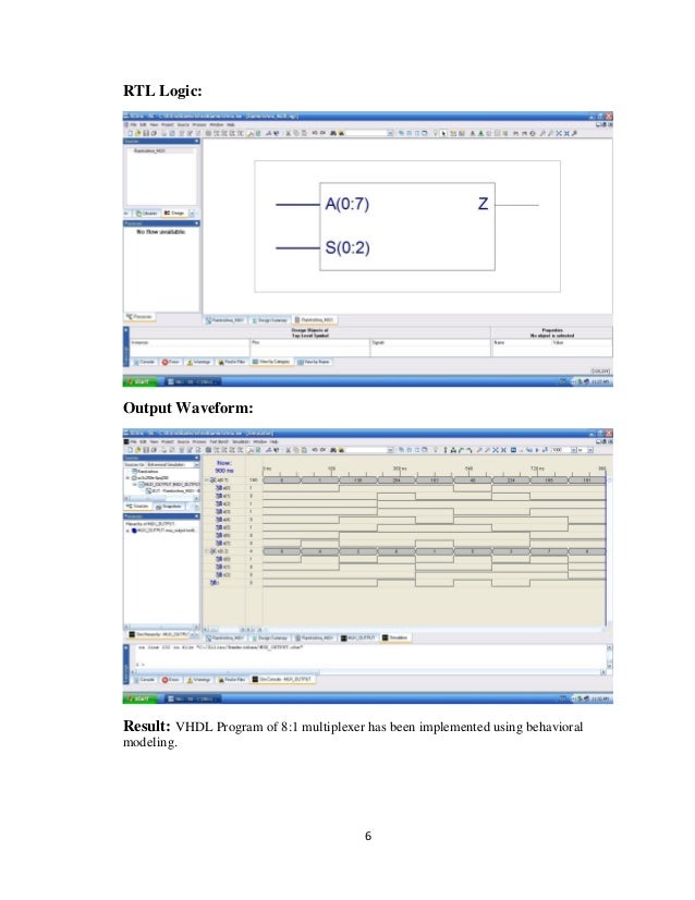
Library IEEE; use IEEE.STD_LOGIC_1164. Chrome Add Ons Youtube Mp3. ALL; use IEEE. Download Lazesoft Recovery Suite Unlimited Edition V3.4.1 With Key T. STD_LOGIC_ARITH.ALL; use IEEE.STD_LOGIC_UNSIGNED.ALL; entity mux8X1 is Port ( en8: in STD_LOGIC; s3: in STD_LOGIC_VECTOR (2 downto 0); i: in STD_LOGIC_VECTOR (7 downto 0); y8: out STD_LOGIC; y8l: out STD_LOGIC); end mux8X1; architecture Behavioral of mux8X1 is begin process(en8,s3,i) begin if(en8='0') then y8y8y8y8y8y8y8y8y8' null'; end case; end if; end process; end Behavioral. Library IEEE;use IEEE.STD_LOGIC_1164.ALL;use IEEE.STD_LOGIC_ARITH.ALL;use IEEE.STD_LOGIC_UNSIGNED.ALL;entity mux8X1 is Port ( en8: in STD_LOGIC; s3: in STD_LOGIC_VECTOR (2 downto 0); i: in STD_LOGIC_VECTOR (7 downto 0); y8: out STD_LOGIC; y8l: out STD_LOGIC);end mux8X1;architecture Behavioral of mux8X1 isbeginprocess(en8,s3,i)beginif(en8='0') then y8elsecase s3 iswhen '000' =>y8when '001' =>y8when '010' =>y8when '011' =>y8when '100' =>y8when '101' =>y8when '110' =>y8when '111' =>y8when others=>' null';end case;end if;end process;end Behavioral. To build a 64 to 1 multiplexer using cascaded 8 to 1 multiplexer, use nine 8 to 1's.
Connect the first 8 to each of the 64 inputs, then connect the ninth to the outputs of the first eight. Connect the three address lines of the eight together to form 3 of the address lines. Connect the three address lines of the ninth to form the other three, for a total of 6 address lines selecting 1 of 64 inputs. This is a lot of logic. Fan-in and fan-out may be considerations.
If you are trying to scan 64 switches, there may be a better way using an 8-bit output connected to a switch matrix (with diodes if you need more than one at a time close-able) and then connected to an 8-bit input. Even better, consider the 8279 keyboard/display controller.